Wiring help

Renault & Alpine General Discussion
User avatar
User

clee

Rank

Non Member

Posts

10431

Joined

Fri May 28, 2004 11:58 am

Location

Derbyshire


Has thanked: 54 times
Been thanked: 104 times

Postby clee » Mon Feb 22, 2010 11:46 am

Yep remove the relay and see if it runs .But as Jon says ,if it's linked to the ECU it can't be for the screen heater .
User avatar
User

chrism

Rank

Non Member

Posts

32

Joined

Fri Nov 04, 2005 8:15 pm

Location

Essex


Has thanked: 1 time
Been thanked: 0 time

Postby chrism » Mon Feb 22, 2010 7:42 pm

Well, with the relay removed and the fried wiring the car started and was running. I then moved some of the other wiring and it cut out and would not re-start. There are one or two other wires that I had already spotted that needed repair so presumably thats the next step.

It certainly looks as though the relay and wiring is heated rear window related then, although the ECU and injector relay wires are a mystery. One of the last things that was done to the car before it came back to me was the rear hatch was fitted back in place and I noticed that the heated rear window wire that had previously been broken, had been repaired and reconnected to the gas strut. I can only presume that that innocent act of repair started the incident. I will pull the fuse for the heated rear window circuit and leave that until I've sorted the other wiring.

Many thanks for your assistance.
User avatar
User

clee

Rank

Non Member

Posts

10431

Joined

Fri May 28, 2004 11:58 am

Location

Derbyshire


Has thanked: 54 times
Been thanked: 104 times

Postby clee » Mon Feb 22, 2010 7:47 pm

Weird, but not unexpected :lol:
Have you found the injector and pump relays ?
User avatar
User

chrism

Rank

Non Member

Posts

32

Joined

Fri Nov 04, 2005 8:15 pm

Location

Essex


Has thanked: 1 time
Been thanked: 0 time

Postby chrism » Mon Feb 22, 2010 8:20 pm

Lee
Injector and pump relays ? - presumably 2 of the other 3 visible in the picture. Any ideas of which is which ?

Image
User avatar
User

JohnC

Rank

Non Member

Posts

2120

Joined

Sun Dec 02, 2007 6:19 pm

Location

Jersey C.I.


Has thanked: 15 times
Been thanked: 83 times

Postby JohnC » Mon Feb 22, 2010 9:18 pm

Well, with the relay removed and the fried wiring the car started and was running. I then moved some of the other wiring and it cut out and would not re-start.

Dont give up on that relay not being the fuel pump one yet.........I was going to post this earlier, but decided to wait till you had checked.
If the burnt wires have infact touched together when the insulation melted, ie: the one going to the relay contact and the other comming from the contact, then of course the car will start. The only difference being is that the pump will be switched on by the ign switch instead of the relay which is energised by a signal from the ECU. The moment you disturb the wiring then the wires can become disconnected and the engin will stop.
I can only go on what you have told us, that being that wires go from the relay to the ECU, and another relay, which still indicates that it must be the pump relay or the injector relay, one cant tell which is which without following the wire to the ECU and determining which pin each relay is connected to. I think I am right in saying that the Le Mans is the D502, if that is right then the pump relay coil pin 2, goes to pin 6 on the ECU, and the injection relay pin 2 goes to pin 7on ECU. But that is only correct if in fact the Le Mans is D502. :wink:
The other point I would make is that the rear screen is fused and as such the fuse would have gone before the wiring passed so much current as to melt them.
Have another look at the wiring and see if you can determine where the wires for the two relays that are joined by a link actuall go to.
1990 GTA Atmo, 2003 Jaguar X type 2.5SE Auto, 2018 Kia Picanto GT-Line-S 1.25
User avatar
User

chrism

Rank

Non Member

Posts

32

Joined

Fri Nov 04, 2005 8:15 pm

Location

Essex


Has thanked: 1 time
Been thanked: 0 time

Postby chrism » Tue Feb 23, 2010 9:20 am

Hi John

Thanks for the response. First of all yes the LeMans is a D502.
Following a brief early morning investigation I came up with the following:

- the yellow wire from the burnt out wiring and relay that goes to the ECU goes to the 6th pin down on the left hand side of the connector (when you have the connector off the ECU and facing you)
- the other yellow wire that goes to the Red Relay is twinned with another yellow wire that goes to a Black Relay.
- The Red Relay has a thick red wire to 12v, thick white that goes up into the engine bay, a small brown wire that goes to the ECU which is the 1st (top) pin on the left hand side of the connector.
- The Black Relay has a red wire, orange wire, 2 yellows, and a small brown that goes to the ECU and is the 17th down (bottom) pin on the right hand side of the connector.

Does this help ?

Cheers
Chris
User avatar
User

clee

Rank

Non Member

Posts

10431

Joined

Fri May 28, 2004 11:58 am

Location

Derbyshire


Has thanked: 54 times
Been thanked: 104 times

Postby clee » Tue Feb 23, 2010 9:53 am

The ecu plug has one row of 18 and one row of 17 .Can you confirm which row you are saying 6 pin down on ,the 18 row ? this should be correct and pin 6 is pump relay .
I have xls doc with all the ecu plug wiring from the Adaptronic install if you want to look at that ?
http://www.store2go.net/shop/renalpserv ... oomST2.xls
User avatar
User

simontaylor

Rank

Non Member

Posts

5603

Joined

Thu Apr 15, 2004 12:33 pm

Location

Fleet, Hampshire


Has thanked: 44 times
Been thanked: 56 times

Postby simontaylor » Tue Feb 23, 2010 10:21 am

Lee, I like the way your link has my initials at the end of it :lol:
Happy to share all information, especially with paid up club members. :lol: :lol:
Come on you free-loaders, :( you can clearly see how this thread is proving so valuable to the club member involved!
1986 : '86 GTA v6 BW-EFR turbo, with Adaptronic ECU
Firsts at
2007 : Gurston Down & RAOC Champion
2008 : Rushmoor & Eelmoor & ACSMC Hillclimb class Champion
2009 : Longcross & Eelmoor
2010 : Crystal Palace & Eelmoor
2016 : Rushmoor & 5th O/A
User avatar
User

clee

Rank

Non Member

Posts

10431

Joined

Fri May 28, 2004 11:58 am

Location

Derbyshire


Has thanked: 54 times
Been thanked: 104 times

Postby clee » Tue Feb 23, 2010 10:24 am

Sorry Mr T .
Do you want I should delete that link :?:
User avatar
User

chrism

Rank

Non Member

Posts

32

Joined

Fri Nov 04, 2005 8:15 pm

Location

Essex


Has thanked: 1 time
Been thanked: 0 time

Postby chrism » Tue Feb 23, 2010 10:43 am

Lee - " The ecu plug has one row of 18 and one row of 17 .Can you confirm which row you are saying 6 pin down on ,the 18 row ? "

When you look at the connector the 18 row is what I called the left hand side, so yes 6th pin down the 18 row - so that really would confirm that it is the pump relay (?).

As this appears to take us back to the initial thoughts could you possibly post a picture of the idle valve to confirm its what I think. Then I can look at the wiring at that end.

Many thanks.
User avatar
User

clee

Rank

Non Member

Posts

10431

Joined

Fri May 28, 2004 11:58 am

Location

Derbyshire


Has thanked: 54 times
Been thanked: 104 times

Postby clee » Tue Feb 23, 2010 11:00 am

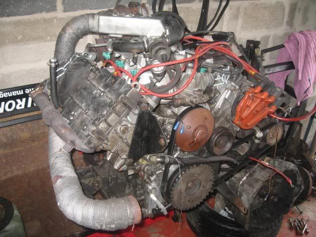
Image

It's the unit sitting on top of the engine just covering the gauge ? Idle bypass valve ,Bosch ,three wire .
User avatar
User

JohnC

Rank

Non Member

Posts

2120

Joined

Sun Dec 02, 2007 6:19 pm

Location

Jersey C.I.


Has thanked: 15 times
Been thanked: 83 times

Postby JohnC » Tue Feb 23, 2010 5:29 pm

Chris, to be honest, I dont think we are going to get fully to the bottom of the third relay, I have 4 injection diags for these Alps, one shows the D501 having a 3 relay system, and the D502 & 501 having a 2 relay system. Even on the 3 relay system, only 2 relays are connected to the ECU. I get the impression from you that your 3 relays are connected to the ECU. My feeling is that the last one you wrote about has nothing to do with the injection system, but I cant tell you what it does, without having more info. Lets say that is right, then the pump relay pin 2... (burnt cable one) is the one connected to pin 6 of the ECU, and your red relay with the thick red wire pin 3, is the injection relay with pin 2 being connected to pin 7 of the ECU, that would tie up with my D502 diag. Going back to your third relay, it could have red and yellow wires coming from the other relays, but as these are voltage feeds, before and after ign, it does not matter, the important info from that relay is where pin 5 goes to.
Just for orentation purposes, which is top and bottom of the ECU plug, Pin 4 should have a red wire (12v permanent) and Pins 1 & 2 should have black wires...negative.
Now that I have got all of that off my chest :lol: ... what to do. We know that the engin ran with the existing wiring, even though it was charred, therefore I would start replacing the wiring one at a time with wire of equal size (current capacity) same colours if pos. I would also bench check the burnt cable relay for operation and short circuits, the covers can be taken off, see if the coil is discoloured. Check the wire comming off pin 5 of the pump relay for charring over its full length which goes to the idle valve if possible, if you are unsure of its condition I would run a new one from relay to the idle valve.
I agree with Martin that it does appear that the charring occured long ago due to its apparent condition, but when did you fit the boost gauge? as I would have thought that you would have noticed the problem.
Hope this is of help :wink:

John
1990 GTA Atmo, 2003 Jaguar X type 2.5SE Auto, 2018 Kia Picanto GT-Line-S 1.25
User avatar
User

chrism

Rank

Non Member

Posts

32

Joined

Fri Nov 04, 2005 8:15 pm

Location

Essex


Has thanked: 1 time
Been thanked: 0 time

Postby chrism » Tue Feb 23, 2010 10:03 pm

I inspected the wiring to the idle control valve and found that the insulation to all threes wires had become brittle and broken (probably from being removed and replaced during the heads off process) and the wires were touching each other. I made good the connections and ran a new centre wire round to the relay.

I then replaced and repaired the other wires (adding in a 10A in-line fuse to the positive).

The car started and ran, but every 10 seconds or so it would nearly die but just recover. It carried on doing this for about a minute then it eventually did cut out. And will not restart, it nearly starts, it skips along trying but not quite makes it.

Can the shorting out have damaged the idle control valve and or relay and now causing this ? I'm going to replace the relay but should I do the icv as well ?

Chris
User avatar
User

clee

Rank

Non Member

Posts

10431

Joined

Fri May 28, 2004 11:58 am

Location

Derbyshire


Has thanked: 54 times
Been thanked: 104 times

Postby clee » Tue Feb 23, 2010 10:09 pm

The valve can be a bit temperamental in it's own right .Give it a spray through with some brake/carb cleaner .It clogs up with oily deposits and sticks .
User avatar
User

JohnC

Rank

Non Member

Posts

2120

Joined

Sun Dec 02, 2007 6:19 pm

Location

Jersey C.I.


Has thanked: 15 times
Been thanked: 83 times

Postby JohnC » Tue Feb 23, 2010 10:55 pm

The car started and ran, but every 10 seconds or so it would nearly die but just recover. It carried on doing this for about a minute then it eventually did cut out. And will not restart, it nearly starts, it skips along trying but not quite makes it.

Umm...I would check the wiring again to make sure there are no loose connections, replacing the relay is a good move,... clean the ICV as Lee suggested, if all else fails there is a possibility that the shorted wires damaged the ECU, but a good check over first before you consider that.
Another thought....I see you have a meter :D , with just the ign on, there should be 12v on pin 2 of each relay, if you get the engin spluttering as before, again pin 2 of each relay will have zero volts on them (the ECU grounds them to energise the relays) if they are both zero then the ECU should be OK.
I then replaced and repaired the other wires (adding in a 10A in-line fuse to the positive).

I am concerned about this, where have you inserted the fuse?,,,,,,the thick wire is there to carry a largish current, I would say 10amps is insufficient, there are a lot of current changes in this type of circuits which fuses dont like and are likely to blow,.....when you are happy that it is running well, I would remove the fuse....it is a weak link. There are good reasons why fuses are not fitted in ign circuits :wink:
1990 GTA Atmo, 2003 Jaguar X type 2.5SE Auto, 2018 Kia Picanto GT-Line-S 1.25
PreviousNext


  • Advertisement

Who is online

Users browsing this forum: No registered users and 17 guests

Powered by phpBB ® | Renault' and 'Alpine' are trademarks of Renault S.A.S. or its subsidiaries and are used with kind permission of Renault France